Geometry as Code: Why Engineering Models Should Be Executable Programs
A geometry program should preserve design intent through parameter edits, not merely reproduce a shape. A mounting bracket shows what that requires.
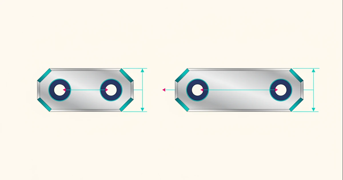
A bracket can look correct while carrying the wrong design intent.
Imagine a component with two mounting holes. In one version, their centers remain a fixed distance apart. In another, each center remains a fixed distance from the nearest edge. The initial shapes might be identical. Widen the bracket, however, and the two designs should behave differently.
That difference is the subject of this research note: what would an executable geometry definition need to preserve beyond the initial solid?
State the relationship before choosing the operation
A proposed definition might expose plate width, thickness, hole diameter, and edge clearance. Hole positions would follow from those inputs rather than from coordinates that happen to work for one size.
For the edge-clearance version, widening the plate would move the holes outward. For the fixed-spacing version, the holes would stay together around the centerline. Neither interpretation is inherently superior; the engineer must be able to select the intended rule.
The program would describe a family of permitted designs, not a single frozen shape.
Give parameters a domain
A diameter is not simply an arbitrary number. The definition should identify its unit, valid range, and relationship to surrounding material.
Suppose an edit makes the hole diameter larger than the space available between the required edge clearances. A credible evaluator would reject that combination or ask the engineer to revise the relationship. Quietly clipping the hole would change the design.
Validity conditions therefore belong alongside construction rules. Successful evaluation should mean that both have been satisfied within the evaluator’s stated capabilities.
Separate a definition from its evaluation
The same bracket definition might be evaluated for interactive inspection, manufacturing exchange, or analysis. Those outputs would need different checks.
An image could help the engineer inspect the layout. A manufacturing representation would require appropriate geometric validity. An analysis model would additionally need materials, loads, and boundary conditions.
Sharing the source definition would not automatically make these outputs equivalent or qualified.
Test edits, not just initial construction
A useful experiment would start with both bracket definitions at the same dimensions, then apply the same sequence of width changes. Expected hole positions should be calculated independently.
Additional cases should include invalid dimensions, a return to the original parameters, and a change that removes a geometric feature. Reconstructing the starting shape alone would miss the central question: did the intended relationships survive?
Programmable CAD is an established idea; OpenSCAD provides a public example of script-driven solid modeling. NeuroCAD’s Universal Geometric Language (UGL) research asks how explicit engineering relationships and evaluation obligations could participate in such a model.
Research note: These proposed workflows do not establish current NeuroCAD feature availability, performance, or engineering qualification.
Discuss NeuroCAD as a pilot or investment opportunity.
Working MVP/demo is available for qualified conversations.
Contact the Founder