From Lattice Geometry to Simulation: Exploring a Connected Workflow
A graded lattice insert illustrates why geometric validity, analysis-domain preparation, and solver verification remain distinct engineering tasks.
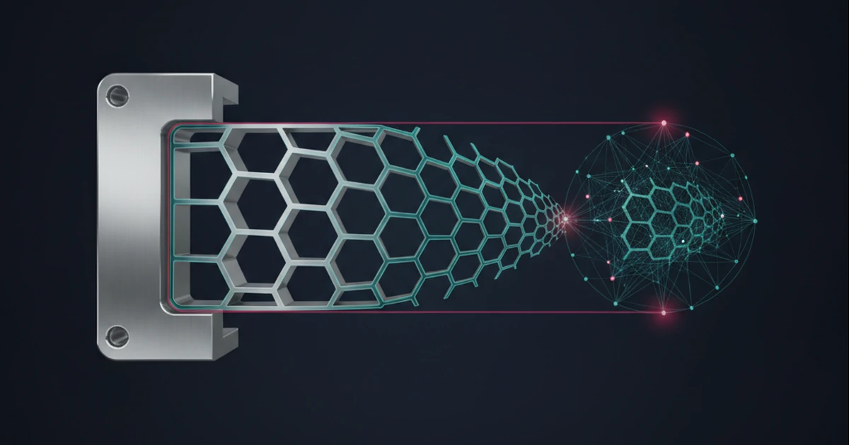
A lattice insert can be easy to recognize and difficult to evaluate.
Changing its cell size or local density may alter connectivity, narrow features, and the way it attaches to a surrounding frame. A rendered image can communicate the concept without establishing whether the resulting part is printable or structurally suitable.
This note follows a hypothetical graded insert from geometric definition toward analysis.
Define the region and its attachment
Suppose an insert fills a bracket’s interior while joining a solid outer frame. The geometry definition must describe both the internal pattern and its relationship to that frame.
Cropping a periodic pattern to the available region does not automatically establish a satisfactory attachment. Disconnected fragments and weakly connected regions are important cases to investigate.
The required connection conditions should be stated before choosing a favorable illustration.
Give grading an explicit meaning
A field might control a local construction parameter across the insert. That creates questions about parameter bounds, transition behavior, and the smallest resulting geometric features.
A field value should not silently stand for several different physical properties. Relative density, effective stiffness, and a manufacturing allowance are not interchangeable merely because they can be visualized with similar colors.
Any proposed relationship between them would require its own evidence and scope.
Prepare the analysis problem deliberately
An analysis may resolve the lattice geometry directly or use an explicitly justified reduced description. These approaches make different assumptions and should be identified accordingly.
A downstream mesh, when required by the selected solver, must be evaluated for the analysis task. Mesh generation success alone does not establish a trustworthy stress or thermal result.
Material definitions, contacts, supports, loads, and solver settings remain part of the study.
Compare engineering outputs, not only shapes
For a bounded investigation, one could examine a small insert family under declared conditions, checking geometry and analysis preparation separately. Refinement studies and appropriate reference cases would help assess the numerical results.
In NeuroCAD’s proposed workflow, the selected physics solver would own the physical computation. The viewport or geometric program would not become the authority for an engineering result.
The potential value of a shared definition is clearer coordination between geometry changes and analysis inputs. It does not remove the need to validate either the lattice construction or the simulation that uses it.
Research note: These proposed workflows do not establish current NeuroCAD feature availability, performance, or engineering qualification.
Discuss NeuroCAD as a pilot or investment opportunity.
Working MVP/demo is available for qualified conversations.
Contact the Founder