Connecting CAD and CAE: Geometry, Meshing, and Simulation
A loaded mounting bracket traces the decisions between CAD geometry, analysis idealization, meshing, solver results, and a reviewed design revision.
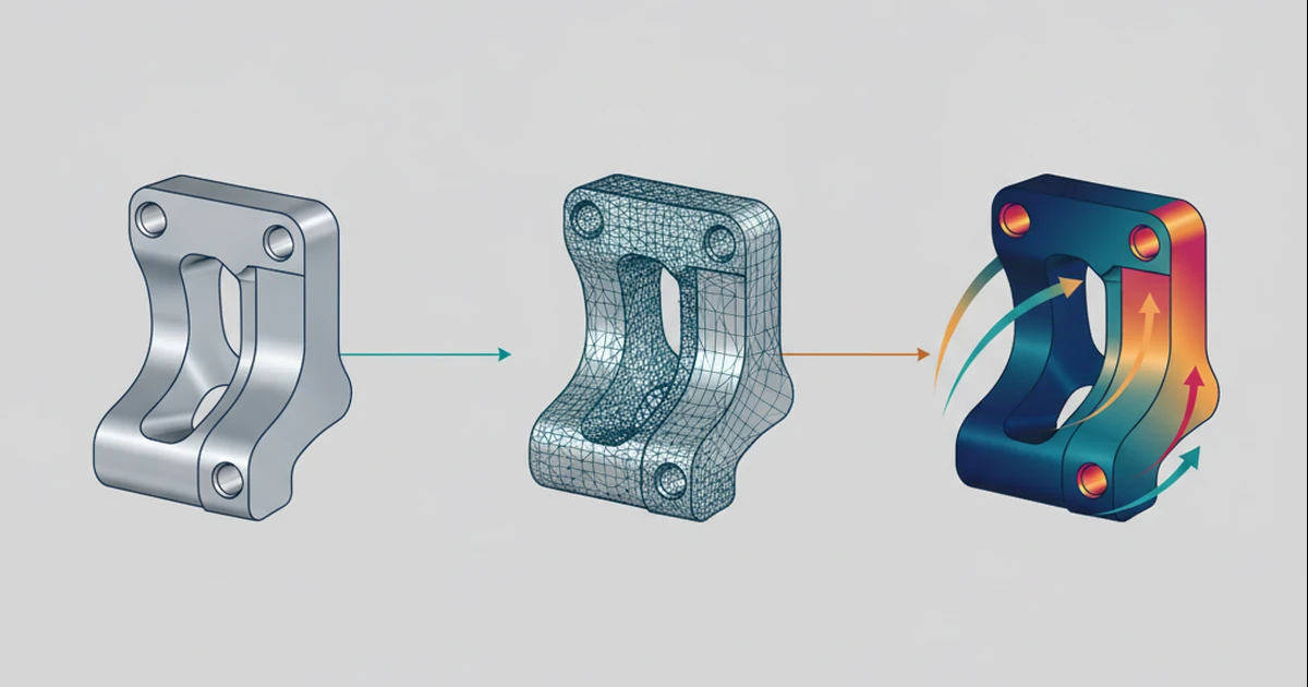
Sending a CAD model to an analysis tool is only the beginning of an engineering study.
Consider a mounting bracket under an applied load. Before a solver can produce an interpretable result, the engineer must choose an analysis idealization, assign material behavior, define supports and loads, and prepare the required computational domain.
A common geometry definition could make this handoff more traceable. It would not make those decisions disappear.
Decide which geometry the study needs
A detailed bracket model may contain small features that are irrelevant to a particular study or expensive to resolve. Removing or simplifying them is an analysis decision with assumptions.
The analysis geometry should therefore be associated with the design revision and the stated simplifications. It should not silently replace the manufacturing definition.
A result obtained from an idealized model must remain identifiable as such.
Preserve meaningful boundary assignments
Suppose the support is assigned to the mounting interface rather than to an arbitrary patch selected in one mesh.
A geometry change can split, merge, or remove the associated boundary. The workflow needs to determine whether the original support assignment still means what the engineer intended.
Keeping an old label attached to a different region would be worse than reporting an unresolved boundary condition.
Treat the mesh as a study artifact
When a selected method requires a mesh, its quality and resolution must be assessed for that problem. A successful export and a visually regular mesh do not establish an adequate numerical solution.
Refinement behavior, solver convergence, and appropriate reference comparisons are separate concerns. Different study objectives may require different preparation from the same source design.
NeuroCAD’s architecture policy reserves these meshes for downstream analysis; the interactive viewport is required to evaluate the SDF geometry directly.
Return results with their assumptions
A stress plot should identify the design revision, idealization, material model, loading, and solver that produced it. The selected physics solver owns that computation.
If the engineer later changes the bracket’s thickness, the old result may remain useful as historical evidence. It should not silently appear as the current answer.
The research objective for CAD/CAE integration is a controlled path from design intent to a well-defined study and back to an informed design decision. Sharing geometric inputs can help establish that path, but cannot by itself qualify the simulation or verify the component.
Research note: These proposed workflows do not establish current NeuroCAD feature availability, performance, or engineering qualification.
Discuss NeuroCAD as a pilot or investment opportunity.
Working MVP/demo is available for qualified conversations.
Contact the Founder